From the moment I got some WS2812B leds in my hands, I wanted to build a led matrix that I could control from my computer. But almost every single project that I found on the Internet used a microcontroller to translate the color data into the stream of bits required by the leds, either by bit banging or with the help of an SPI port. I found that there are some modules specifically designed for this task, but with a price tag that seems excessive to me.
Since a PC has enough power to do the translation itself, the only problem is to find an appropriate output for the bit stream. And since at least my PC has no SPI port, the next obvious candidate is the serial port.
After reading a blog post about the WS2812B timing by Josh Levine I knew that I was on the right track, specifically where he wrote:
People have used many exotic and complex methods to meet these strict requirements- including cycle counting, PWM, SPI, and even UARTs with extra inverter hardware
So yes, I’m about to use an exotic method (but not complex at all): an UART with extra inverter hardware. In that blog post he also states that the only critical parameter is the maximum width of a 0-bit pulse (500 ns). This value gives a minimum frequency that the UART has to support: 2Mbps.
Forming the bit stream
If we compare the signal required by the WS2812B with the one generated by an UART, they would seem incompatible especially because the UART signal has start and stop bits that should always be sent and thus would interfere with the intended signal. Also, the timing doesn’t appear to match the timings in the WS2812B datasheet. But we are working under the asumption that the only critical value is the bit-0 time: if bit-0 time equals x, bit-1 time would be 2x and the full period would be 3x, thus we could produce a nice signal that is still within specs.
How would this bit stream look, if it was composed of 0 and 1 bits alternated? How can we coalesce this sequence with the UART’s sequence?

Because each WS2812B bit always start with a high level and ends with a low level, we could consider that the WS2812B signal also has start and stop bits surrounding each data bit, altough with inverted levels when compared to an UART. So the same WS2812B bit stream from previous picture could be visualized as:

Since the start and stop bits are inverted with respect to the UART’s signal we invert every bit in the previous sequence to get the sequence to send over the UART:
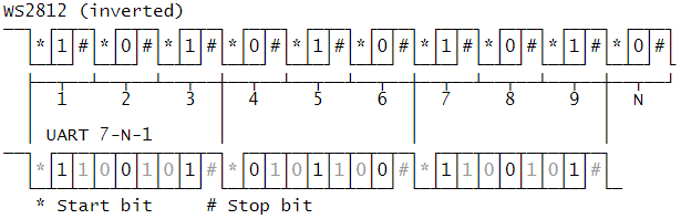
The UART can be configured to send only 7 data bits, which gives a total of nine bits sent for each byte, and this matches three WS2812B bits. And because a single pixel requires 24 bits this means that the whole color sequence could be encoded in exactly 8 memory bytes. In the figure above the values in gray are constant so they help to build a template or map to place the color bits. Remember that the UART sends the LSB first so to visualize the real value to encode, just reverse bit positions as in the following figure:
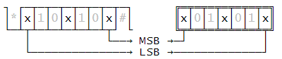
Let’s see an example. To send the color orange (0x05ff00 in GRB), starting with the MSB we’ll divide the color bits in eight groups of three bits, and using the template above we’ll find the value to send over the UART. Remember that we have to reverse and invert the bits to match UART’s bit order and levels:

Because there are only eight three-bit permutations, a simple way to solve the bit encoding is to use a lookup table:
byte[] bitTriplets = new byte[] {
    0x5b, 0x1b, 0x53, 0x13,
    0x5a, 0x1a, 0x52, 0x12
};
Put everything together
To test this idea we need an USB to serial converter capable of at least 2Mbps but we can go as high as 3Mbps with 2.4Mbps being the one producing the closest timing with the one specified in the datasheet.
An ubiquitous device with this capabilities is the FT232R. So I tried first to use this module because I have one at hand and according to the datasheet you can invert the TX signal by flipping a bit in the firmware. But it turns out I have a counterfeit product so I had to invert de bits externally. A simple inverter using a general purpose transistor does the job:
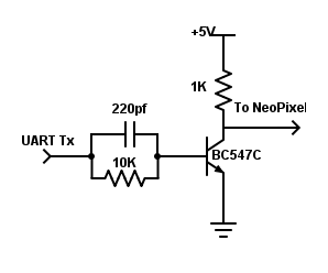
With the above circuit and a simple “chasing” program I tested the idea with the FT232R and the CH340 which I also had lying around.
You can download the complete source code from the github repository.

Very cool! It is even possible to do with without an inverter if you muck with the serial port enough…
https://wp.josh.com/2014/09/03/inside-neouart-tricking-a-serial-port-into-being-a-signal-generator/
LikeLike
Thank you Josh for taking the time to comment. It seems that I didn’t search hard enough, if I had read that blog post I could have saved many hours. I will check into the break signal for the Usb bridges that I have. Thanks again, without your analisis I couldn’t have had the idea in this post.
LikeLike
I’d like to control a led strip of 300 from my PC, by sending it data in real time (30FPS will do).
Is this possible to do with your code?
I don’t have much free time, and want to use the little I have to mess with the code that generates the data, if it is possible.
How can I get up and running as fast as I can? (I will, of course, learn everything when I’ll have free time)
Did you maybe find a way to do it without any extra hardware?
If not, what do I need to run 300 leds at at least 30FPS? (of course, the smoother the better)
Thanks for doing the experiments and sharing the results with us hobbyists 🙂
LikeLike
Noam,
I’ve been really busy (and also I’m very lazy), so I haven’t published the second part that I planned for this blog post. But yes, even the slowest device that I tested, the CH340G can handle up to 512 leds at about 50 FPS. But for simplicity I recommend you to use the FT232R: Although expensive, you can invert the output from the firmware, and thus is the simplest set up for what you need.
LikeLike
I succeeded!
My FT232 was not counterfeit (checked by the link you provided) and it worked without an inverter!
I ran a strip I had of 60 leds and it worked flawlessly, but I have a problem running it through a strip of 300 leds.
This is what happens:
I connect the strip, it lights up with a gradient of white to orange to red (as I don’t have enough energy, but I just wanted to check if the animation works before I get a supply)
And when I ran your code, the amount of leds I declared in the variable “pixelCount” go black, and the rest of the leds get the remaining energy (e.g If I use a pixelCount of 250 (out of 300), 250 leds will turn off, and 50 leds will be fully white).
Do you have any idea what I am doing wrong?
Thank you for your reply (even though you are a self-declared “lazy”).
LikeLike
Hello,
You really have to either invert the signal from firmware or with an external inverter.
I think the timing is correct as the number of leds you have defined are being turned off, but you’re seeing a reset pulse, since the iddle TX line is low and this is interpreted as a reset by the pixels.
Invert the line. It works:
LikeLike
As I wrote, I did invert the signal, from firmware, with the FT232, and it did work with a strip of 60 leds, but it doesn’t work with a strip of 300 leds.
Then, what am I still doing wrong?
LikeLike
Sorry. I thougt you didn’t change it. It might be an issue with the baud rate. Have you tried different values? I found that if you mix different pixel types you might get errors. Try with lower baud rates. 2Mbps or 2.4Mbps.
LikeLiked by 1 person
You nailed it!
It works like a charm with 2.4Mbps 🙂
LikeLike
Also… the power. All those leds might be sucking too much power and the signal might be corrupted.
LikeLiked by 1 person
You were right about this too, I added this line to your code:
refValues[i] /= 16;
And any funky behaviors were gone.
Thanks again.
LikeLike
I have an issue where only the first LED will light up green. No other LEDS turn on. I’ve tested this on two different ft232r cards. Do you have any ideas as to what could be happening?
LikeLike
Hello,
Please ensure that you inverted the TX signal with the FTDI utility. You could also start with a different Baud rate, acceptable values are 2000000, 2400000, 3000000.
Try from lower to higher. I have found leds that work with baud rates as low as 1200000. So try to use leds from the same manufacturer…
LikeLike
Hi there,
I’m driving nearly 900 pixels (3 strips powered by 3 5v10a power supplies, connected in series) from an Adafruit FT232H and ran into an issue – which maybe others will as well.
I was having really weird problems with what seemed like data corruption. Initially just connecting my pocket scope or any resistor (which many designs call for on the data line) caused problems – and that got me thinking.
So, as it turns out, the FT232H (which is called a 5v board) has an SPI output of 3.3v. The Neopixels call for 5v and will tolerate about 70% of that (so about 3.5v) – so there is the problem. At this point, I ran the output through every level shifter I could find – with no luck. Then (about to give up), I tried a 74AHCT125 and it works!
I can run patterns up and down the lights without issue – until i move the computer mouse?!?
Any ideas anyone?
LikeLike
I have not tested this particular device, although I’m sure it should work if it’s configured as UART. But if you use my code, you’re going to be limited by the Virtual Com Port driver. For the FT232R the driver sends data in 4KB chunks so you can only drive reliably 512 leds and I guess the FT232H have probably the same limits. Assuming there is no other device on the bus competing for it, you might get lucky and see no glitches, but as I said before its not reliable beyond 512 leds. To control more leds I simply connect more UARTs, and so far I’ve been able to control 12800 leds with 25 UARTs (PL2303 & CH340) and some MTT USB Hubs.
I have tested the direct Driver from FTDI and it allowed me to control more leds, but my intention was to use cheap USB to UART devices. You might try the direct API, since the FT232H has a transmission buffer double the size of the FT232R, I guess 900 leds won’t be an issue.
LikeLike